What is GISS?
Download book in PDF, 5Mb1.3 System technical concept
1.3.1 The system is created in stages based on an orbital constellation of 72, 144, 288 or 576 spacecraft (SC) of two types, connected by inter-satellite communication links located respectively in 6, 9, 12 or 24 orbital planes in low orbit (from 400 km to 800 km) and a territorial network of distributed ground points for receiving and processing GISS signals in the countries participating in its creation and operation, as well as various terminal equipment for satellite communications for personal and collective use.
1.3.2 Global and practically continuous radar sounding of the earth's surface and near-earth space is carried out by the method of active-passive multiposition three-dimensional radiolocation, in which the sounding signal is emitted by one type of spacecraft, and the reflected signals are received simultaneously by three or more spacecrafts of a second type and in digital form together with data about ephemeris and onboard time of the spacecraft are relayed to ground receiving and processing points, where:
- archiving of sounding and received reflected signals in a wide observation area for the possibility of analysis and investigation of emergency events that occurred in the past;
- synthesis of the received reflected signals with a narrow radiation pattern from the required control area of the mobile and stationary objects of interest;
- cross-correlation processing of probing and received different-angle reflected signals, synthesis and thematic processing of a 3D image in almost real time (depending on the performance of computing processing complexes).
1.3.4 Each spacecraft from the GISS orbital constellation emits high-power sounding signals only in one of the two frequency ranges intended for satellite radar (L-band or X-band), and receives reflected signals in the other, which allows electromagnetic compatibility (EMC) to be provided on the spacecraft itself. Thus, the system uses, as it were, a common frequency band on the “up” and “down” links relative to one repeater of the GISS spacecraft in comparison with conventional radar and communication systems. This ensures high reliability of operation due to duplication of paths for receiving important messages by three spaced satellites.
Accordingly, the constellation contains two types of spacecraft located in the orbital plane through one (even — L / X and odd — X / L transmission / reception range). A fragment of the GISS orbital constellation is shown in Fig. 1.1
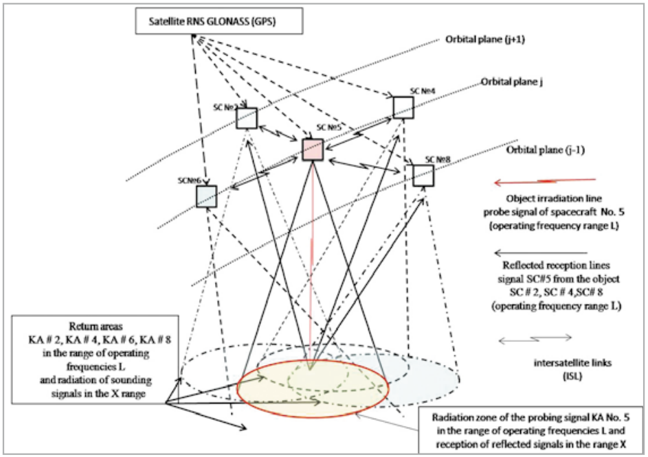
- Fig. 1.1 Fragment of the orbital constellation GISS
Onboard special complexes of the GISS spacecraft are, in essence, communication satellites with onboard signal processing and have nothing to do with traditional spacecraft radar sensing. This provides a high economic efficiency of the creation of GISS. With continuous global radar monitoring of the earth's surface and nearearth space, a high-performance global low-orbit communication system is being created, technologically simpler and cheaper due to the use of the mastered Land X-frequency bands, compared to projects such as OneWeb and Starlink (SpaceX), operating with expensive ground-based terminals in the millimeter range.
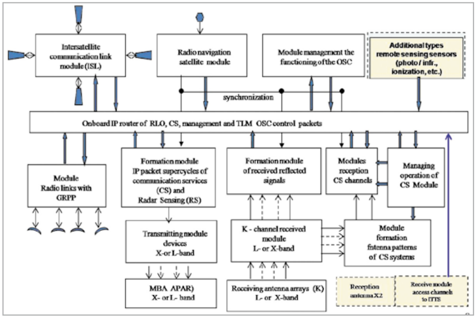
1.3.5 For reception, multi-element antenna arrays (AA) are used with a number of elements sufficient for the subsequent formation of narrow beams on the Earth that scan in the radar monitoring zone, and for transmission, relatively small-element active electronically scanned array (AESA) are used, providing the formation of beams from the global in the current service area for communication services to the required narrow beam, providing detection of stealthy targets for radar. The use of antennas spaced apart on adjacent satellites for receiving and transmitting in theLand X-bands makes it possible to realize the maximum power and coefficient of efficiency of the transmitting AESAs and the minimum noise figure of the receiving AA elements.
The generalized structural and functional diagram for two on-board special complexes (relay satellites with onboard signal processing) is shown in Fig. 1.2.
1.3.6 Reflected signals received by each AA element when observing objects in an area with a diameter of 4—5 thousand km are relayed to ground receiving and processing points directly when they are in the same visibility zone. Or / and through a network of neighboring satellites (two in its orbital plane and two in adjacent planes) under radar control, for example, the Antarctic zone from the Moscow Region point or the Faroe Islands from England. These signals are retransmitted in digital form without on-board phase and amplitude control, which allows each ground receiving point to generate one or more virtual radiation patterns (RP) of the on-board receiving antenna and / or radiation patterns required for object tracking required for broadband communications applications.
1.3.7 Inter-satellite communication links (ISL) are created by 4 links for each spacecraft. ISLs can be implemented with optical laser lines with a bandwidth of about 20 Gbps. Laser ISLs can be created between spacecraft along the orbital planes of the GISS space constellation. ILS between spacecraft located on adjacent planes of the GISS orbital constellation, due to the high angular velocity of their mutual displacement, it may be more expedient to create in the TeraHertz wavelength range with an adaptive information transfer rate from 4 to 10 Gbps, depending on the energy parameters of the ILS and variable range of radio links.
1.3.8 High-speed feeder communication lines with ground receiving and processing stations (4 for each spacecraft) are implemented in the Ka-band using highly directional tracking antennas on board and on the ground. The bandwidth of the information drop on the downlink feeder line should (can) be provided for about 8 - 10 Gbps. Four sets of feeder lines are created to provide the possibility of simultaneous relaying of signals to ground receiving points in three neighboring countries or three regions of one country with a large territory. Conventionally, the“fourth” set of the transmitting and receiving feeder line of each spacecraft is in the programmed re-targeting mode to the next ground receiving and processing point in the current service area.
1.3.9 Routing of IP packets in GISS for all radar and communication applications, telemetry and on-board control complex is carried out by on-board high-performance routers as part of on-board special complexes (OSC) of spacecraft — repeaters of communication satellites.
1.3.10 The composition and structural-functional diagram of the GRPS-ground station for receiving and processing GISC signals is shown in Figure 1.3.
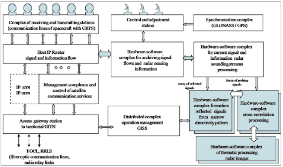
1.3.11 The complex of receiving and transmitting stations (RTS) of the Ka-band provides tracking of spacecraft in the visibility zone, receiving downward signaling and information streams and transmitting upward streams of communication service packets, control commands, retrieving telemetric information and other types of service information for managing the provided communication services. The number of RTS corresponds to the number of the GISS spacecraft in the service area plus two stations for reservation and re-targeting to a new spacecraft entering the service area of this signal receiving and processing point.