What is GISS?
Download book in PDF, 5MbENERGY CALCULATIONS OF RADAR DETECTION
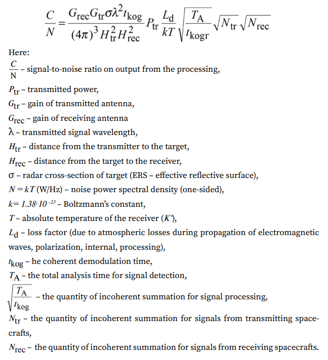
This well-known final formula for estimating the ratio of the reflected radar signal energy to the noise energy in the target acquisition decision path is, in principle, correct, but it does not allow one to see the signal-to-noise ratios on various reception, relay and ground signal processing paths, the knowledge of which is very important in design hardware and software GISS.
Therefore, in this section, the calculated values of the signal-to-noise ratios are given depending on the selected parameters of the receiving-transmitting antenna systems, their values at various stages of onboard reception and signal processing in the ground complex.
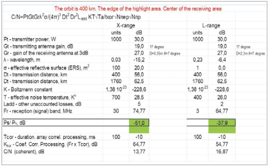
To assess the possibility of continuous radar observation of the earth’s surface and near-earth space, tables A2.1÷A2.3 show calculations of the possibility of energy detection of targets with an ERS (σ) equal to 1 m in the L-band and 100 m in the X-band for three altitudes orbits of a constellation of 288 GISS spacecraft.
The radiation power in all versions is taken equal to 2 kW, the targets are located at a range corresponding to the worst case of their location at the edge of the visibility zone of one of the GISS spacecraft.
The values of the remaining parameters are given in the tables; when implementing detection by the criterion of maximum likelihood, the ratio S/N> 10 dB is taken beyond the boundary of confident detection.
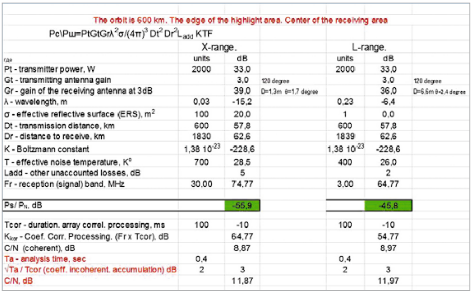
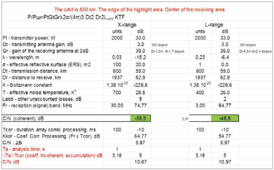
The calculations were performed for three variants of orbit heights of 400 km, 600 km, and 800 km.
Analysis of the table. A2.1 shows that from an altitude of 400 km, by emitting signals through an omnidirectional antenna with Gt = 3 dB into a full wide area in an illumination angle of 120°, it is in principle possible to ensure the detection of targets with the indicated ERS values.
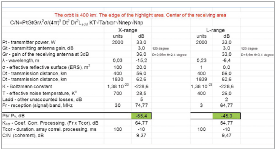
For this, during ground processing, the duration of the coherent accumulation array must be at least 100 ms, and the receiving antenna array on board must be implemented with the specified parameters and the most difficult problem of synthesizing narrow radiation patterns during ground processing must be solved by operating with partial signals at the output of each of the AE in a digitized form with SNR ratios lying at a level of minus 55÷75 dB below the noise in the indicated signal bands. More promising such a mode of continuous radar monitoring of small targets can be implemented only in the L-band.
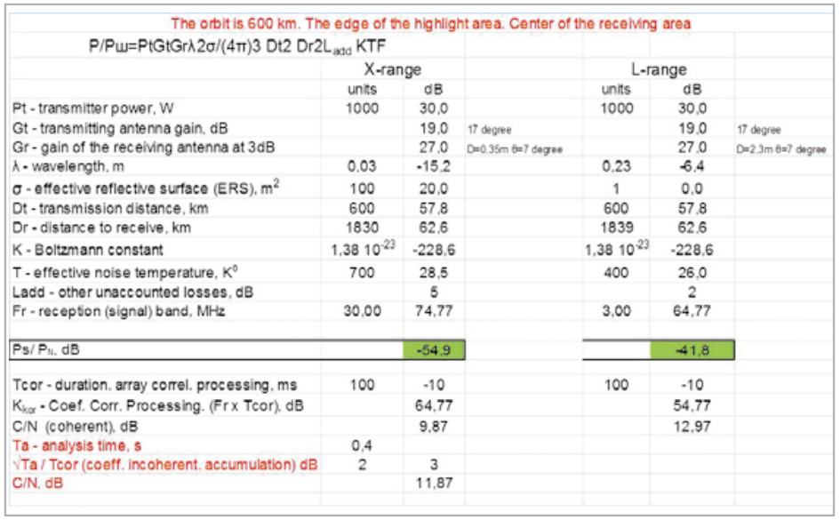
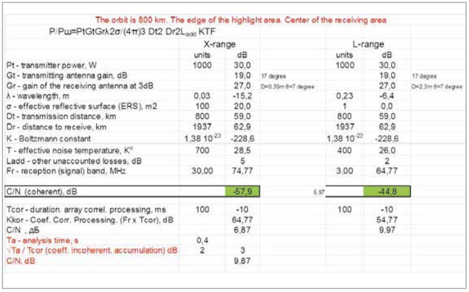
Analysis of calculations in Tab. A2.2 and A2.3 also show the theoretical possibility of ensuring the implementation of continuous radar monitoring of the entire visibility zone. However, the requirements for the implementation of receiving antenna arrays on board the spacecraft and the duration of the processed signal arrays on the total processing interval of 0.4 s and 1.0 s, respectively, using incoherent accumulation of the energy of reflected signals, are increasing.
With such parameters of the on-board antenna systems allowing continuous radar control, the possibilities of ensuring high throughput of communication channels and the flexibility of its redistribution within the territory of the global service area are reduced.
So, in the L-band, even from an orbit altitude of 400 km on the downlink, the throughput will be limited to no more than 20 Mbps for terminals in an omnidirectional antenna. In the X-band – generally up to 200 kbps.
Consequently, it is advisable to limit the concept of continuity by providing solutions to a variety of applied problems. So, to control the state of strategic forces and the location of the Navy, it is sufficient to monitor the areas of near-earth space and in tens of minutes. The issues of the subsequent investigation of terrorist acts and the search for missing aircraft (such as events with the MH 370 airliner) require a review period of up to 10 seconds.
Since the modes of operation of on-board special complexes are under control, we will consider it as an “international consortium”, then depending on the military-political situation and current regional problems and taking into account the provision of communication services, appropriate modes of radar sensing can be established.
Suppose that the mode is selected in which the power of 2 kW is divided in half, 1 kW for radar sounding with a scanning beam in the eighth section of the band of the radar sounding range, and seven other bands (see Fig. 2.12) are used to provide communication services with the required redistribution of the total power in 1 kW between partial service areas.
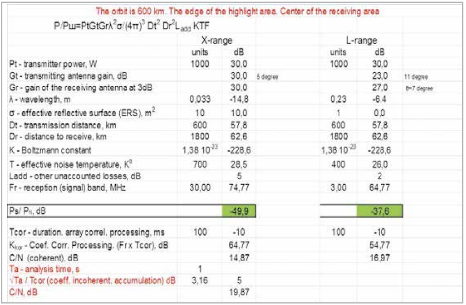
The calculation results for three variants of the orbital heights of the orbital constellation are given in Tables A2.4÷A2.6. In the tables, the transmitting antenna gain is 19 dB, which provides scanning of 37 sections of the global visibility zone with an angle of 120 degrees. The gain of the receiving ensures the formation of a narrow beam of 7 degrees on the ground based on the antenna array shown in Fig. 2.7.
As you can see from the table A2.4–A2.6 in the L-band at any altitude from 400 km to 800 km provides reliable detection of targets with an ERS of 1 m or more.
At the same time, the frequency of repeated, as it were continuous observation, in the equatorial regions of +/- 20 degrees can be ensured in 3.7 s, at which the airliner or unmanned aerial vehicle will not go anywhere during the subsequent investigation of emergencies.
In the northern populated and important areas from 40 to 60 degrees N, the distance between the orbital planes narrows, therefore, sounding with a transmitting beam at 19 degrees can be done in 19÷21 partial zones. In this case, the frequency of “continuous” observation will be provided for about 2 seconds. In the Arctic zone of intersection of orbital planes, sounding can also be carried out in seven adjacent directions, guaranteeing the periodicity of monitoring possible missile launches from a submerged position in 0.7–1.0 seconds.
For this variant of the configuration of the parameters of the onboard transmission and reception paths in the L-band on the downlink, the information transfer rate to terminals with a low-directional antenna (3 dB) from 2 Mbps to 30 Mbps can be provided, depending on the location in service area and orbit altitude. For terminals with directional tracking antennas, the on-demand bit rate will accordingly be k (dB) = (Gr – 3 dB) higher.
When designing the GISS, it is necessary to implement on-board transmitting and receiving paths with parameters that can be achieved taking into account the energy and mass limitations on the spacecraft, which allows group output of 12 vehicles with one launch vehicle.
Table A2.7 shows the calculations for one of the possible implementation options with the given parameters of the spacecraft onboard paths.
As can be seen from the table, with such quite realizable parameters, even in the X-band, the detection and tracking of targets with the ERS (σ) equal to 1 m can be provided. In the L-band, such detection can be provided with the correlation accumulation of the reflected signal energy for 20–30 ms.
When creating a GISS with an orbital constellation of 576 spacecraft, the joint vision zones of four spacecraft are almost halved, and solutions for quasi-continuous radar surveillance and communication services with spacecraft visibility angles of more than 10 degrees of an extended simplified mode of operation of onboard repeaters.
In the field of existing estimates of the ERS values of targets, it should be noted that they are obtained for the existing principles of radar operation. For the proposed method of active-passive 3D radar, the better the target corresponds to the stealth technology, which reflects the bulk of the radar pulse energy not towards the radar, the better its detection in the GISS orbital constellation. For this method, the best type of “corner reflector” is the ball head of the rocket taking off.
All calculations and possible limitations associated with complex in implementation algorithms of ground processing will be clarified when implementing the experimental fragment of the GISS.